The 30-Second Trick For Wedge Barriers
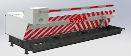
In the adhering to discussion, reference is made to a surface of a foundation to which the wedge-style obstacle is mounted. In the illustrated embodiments, the upper side of the support is significantly flush with the surface area of the structure. In such embodiments, the wedge-style obstacle might be mounted straight to the surface of the foundation. However, in other personifications, the top side of the anchor might be somewhat elevated above the surface of the foundation or a little recessed listed below the surface of the structure. 1 is a front perspective sight of an embodiment of a surface-mounted wedge-style barrier 10. As revealed, the barrier 10 is mounted to a surface 12 of a foundation 14(e. g., a shallow structure ). The structure
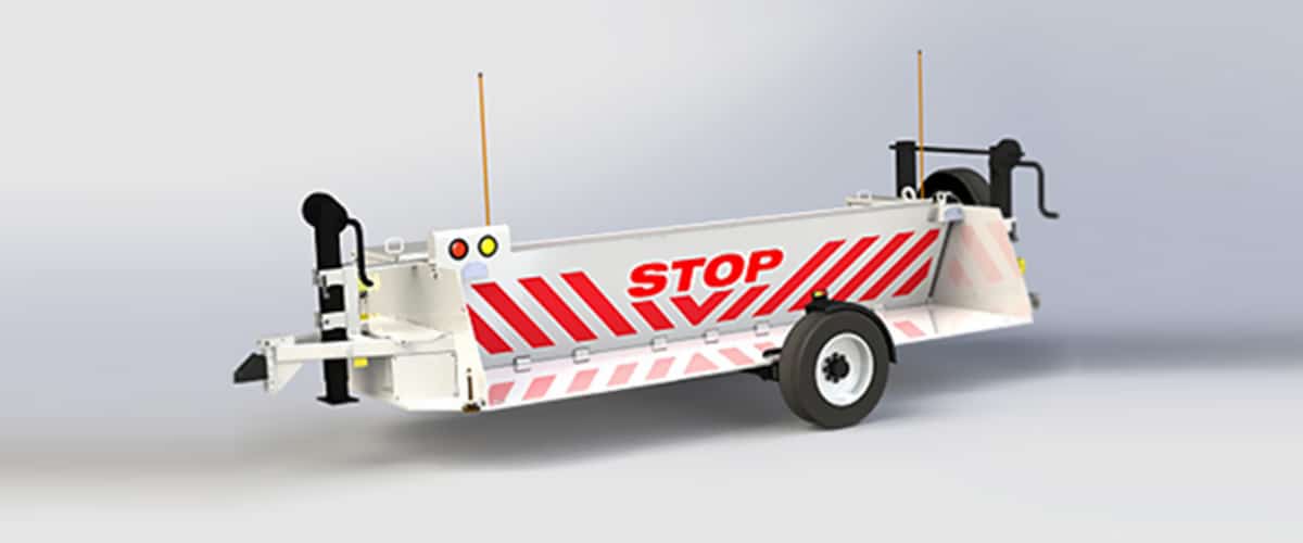
14 and the surface 12 to which the barrier 10 is secured may safeguarded might from concrete. 2, the obstacle 10 is installed to or includes an anchor or subframe (e. g., anchor 30 received FIG. 2 )secured underneath the surface 12. For example, the bather 10 may be bolted to the anchor or secured to the anchor by other mechanical fasteners. In the detailed personification, the obstacle 10 consists of a wedge plate 16, which consists of a portion that is considerably parallel with the surface 12 when the obstacle 10 is in the retracted placement. Simply put, vehicles or people may pass over the barrier 10 when the barrier 10 is in the pulled back setting and experience small altitude about the surface 12 while on the obstacle 10. As gone over in information listed below, when the obstacle 10 is in the deployed placement, the wedge plate 16 is held and sustained in an elevated placement by a training device of the barrier 10. In addition, the elements 18 may be bolted or otherwise mechanically combined to each other. In this way, fixing or substitute of one or more elements 18 may be simplified and streamlined. That is, fixing or substitute of single components
18 may be done much more swiftly, easily, and cost properly. FIG. In particular personifications, the support 30 may be a steel structure including plates, light beams(e. g., I-beams ), and/or other structures that are secured within the structure 14, which may be concrete. At the surface 12, a top side 28 of the anchor 30 might be at least partly exposed
, therefore allowing the attachment of the barrier 10 to the support 30. g., threaded openings)in several beam of lights or plates of the anchor 30 may be subjected to the surface 12. In this way, screws 32 or various other mechanical fasteners might be utilized to protect the obstacle 10 to the support 30. As the barrier 10 is placed to the surface 12 of the foundation 14, collection of debris and other material under the barrier may be lowered, and components of the bather 10 might not be subjected to listed below quality atmospheres. As shown by reference character 52, the lifting mechanism 50 consists of elements got rid of below the wedge plate 16. As an example, the parts 52 beneath the wedge plate 16 might include an electromechanical actuator, a webcam, one or more cam surface areas, and so forth. In addition, the lifting system 50 consists of a spring assembly 54
The springtime pole 58 is coupled to a webcam(e. g., webcam 80 received FIG. 4) of the lifting system 50. The springtimes 60 disposed regarding the spring rod 58 are held in compression by springtime supports 62, consisting of a taken care of springtime support 64. That is, the set spring support 64 is fixed loved one to the foundation 14 et cetera of the bather 10.
The Ultimate Guide To Wedge Barriers
g., springtime assistance 65 )might be taken care of to completion of the springtime pole 58 to allow compression of the springs 60. As the springtimes 60 are pressed in between the springtime sustains 62, the springtime assembly 54 generates a force acting upon the camera coupled to the springtime pole 58 in a direction 66. The staying force applied to
the cam camera deploy the wedge plate 16 may might provided by an electromechanical actuator 84 or other various other. The spring setting up 54 and the actuator 84(e. g., electromechanical actuator)may operate with each other to equate the cam and lift the wedge plate 16.
As discussed above, the spring setting up 54 applies a constant force on the cam, while the electromechanical actuator might be managed to put in a variable pressure on the camera, consequently making it possible for the training and reducing( i. e., releasing and retracting )of the wedge plate 16. In particular personifications, the continuous force applied by the spring assembly 54 may be adjustable. g., electromechanical actuator) is handicapped. As will be appreciated, the springtime setting up 54 may be covered and protected from debris or other components by a cover plate(e. g., cover plate 68 revealed in FIG. 4) that may be considerably flush with the raised surface area 38 of the foundation 14. As pointed out over, in the released setting, the wedge plate 16 serves to block access or travel beyond the barrier 10. As an example, the barrier 10(e. g., the wedge plate 16 )may block pedestrians or automobiles from accessing a home or path. As discussed above, the barrier 10 is affixed to the support 30 secured within the foundation 14,

front braces 71. Because of this, the click now affiliation assemblies 72 may pivot and revolve to enable the collapse and expansion of the affiliation assemblies 72 throughout retraction and deployment of the bather 10. The affiliation assemblies 72 cause activity of the wedge plate 16 to be limited. For example, if a vehicle is traveling in the direction of the released wedge plate 16(e. For instance, in one scenario, the security legs 86 may be extended duringupkeep of the barrier 10. When the safety legs 86 are released, the safety and security legs 86 support the weight of the wedge plate 16 versus the surface 12. Because of this, the lifting mechanism 50 may be shut off, serviced, gotten rid of, replaced, etc. FIG. 5 is partial viewpoint sight of an embodiment of the surface-mounted wedge-style barrier 10, highlighting the cam 80 and the web cam surfaces 82 of the lifting mechanism 50. Especially, two cam surface areas 82, which are referred to as reduced web cam surfaces 83, are placed listed below the webcam 80. The reduced webcam surface areas 83 might be taken care of to the surface area 12 (e. For example, the lower camera surface areas 83 and the placing plate 85 may develop a solitary item that is secured to the anchor 30 by screws or various other mechanical bolts. In addition, two cam surfaces 82, which are described as top camera surfaces 87, are placed above the camera 80 and combined to (e. In various other personifications, intervening layers or plates might be positioned between the surface 12 and the lower webcam surfaces 83 and/or the wedge plate 16 and the top web cam surfaces 87 As mentioned above, the web cam
80 converts along the web cam surfaces 82 when the wedge plate 16 is lifted from the retracted position to the deployed placement. Furthermore, as mentioned over, the springtime setting up 54 (see FIG. 3 )may offer a force acting on the cam 80 in the direction 102 using springtime pole 58, which might lower the force the electromechanical actuator 84 is called for to relate to the webcam 80 in order to activate and raise the wedge plate 16. 1 )to the deployed setting(see FIG. 4). check this site out As revealed, the web cam 80 consists of track wheels 104(e. g., rollers), which contact and equate along the webcam surfaces 82 during operation.